

NEWS
News information
Subcategory:
When engineers select an optical linear encoder, attention often goes first to measuring length, grating pitch and resolution. Those parameters are important, but they do not tell the entire story. The encoder’s output signal must also match the controller, interpolation electronics, cable environment and motion requirements of the machine.
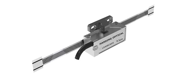
A mismatch at the signal level can produce unstable counts, limited speed, positioning noise or an integration project that requires unexpected electronics. This is why two exposed linear encoders with similar mechanical dimensions may behave very differently after installation.
At DONGGUAN CITY HANDING OPTICAL INSTRUMENT CO., LTD., we develop optical linear encoders, linear scales and precision measurement equipment. Our work with both encoder components and Video Measuring Machines allows us to consider the full feedback chain—from the grating scale and readhead to the controller and application software.
This guide explains how TTL and 1 Vpp signals differ, where interpolation enters the system and which questions should be answered before selecting a linear encoder.
What the Readhead Actually Produces
An optical encoder readhead detects periodic markings on a linear scale. As the readhead moves relative to the grating, the optical system converts the pattern into electrical signals that represent displacement.
Many incremental encoders provide two channels separated by approximately 90 electrical degrees. These channels are commonly described as A and B. Their phase relationship allows the controller to determine direction. A reference mark may provide an additional repeatable position for homing or machine initialization.
The form of the A/B information depends on the encoder interface. Some readheads deliver square-wave digital signals, while others provide analog sine and cosine signals that require interpolation.
The correct choice depends not only on desired resolution, but also on the input accepted by the motion controller.
TTL Square-Wave Output: Integration Simplicity
A TTL-type incremental encoder generally supplies digital A and B square-wave signals. Differential line-driver formats are commonly used in industrial motion systems because the receiving circuit can compare complementary signal pairs and reject part of the electrical noise shared by both conductors.
With quadrature counting, the controller can detect transitions on the A and B channels to obtain a count rate higher than one count per complete signal period. The usable resolution is determined by the encoder output subdivision and the controller’s counting method.
TTL output offers several practical advantages:
direct compatibility with many PLCs, counters and motion controllers;
straightforward wiring and signal diagnosis;
no separate analog interpolation stage in many installations;
convenient replacement in machines already designed for digital encoder inputs.
However, “digital” does not mean immune to installation problems. Long cables, poor shielding, incorrect grounding, damaged connectors or insufficient receiver bandwidth can still cause missed or false counts. The controller must also support the encoder’s maximum output frequency at the required travel speed.
A high-resolution output produces more pulses per unit of movement. At high axis speed, the pulse frequency rises accordingly. Engineers should therefore check both resolution and frequency capacity rather than evaluating either value alone.
1 Vpp Analog Output: Flexible Interpolation
A 1 Vpp encoder typically outputs analog sine and cosine signals. Instead of treating each grating period as a single digital event, an interpolation circuit analyzes the signal phase and subdivides that period into many smaller position increments.
This architecture gives the machine designer flexibility. The same basic grating signal may support different digital resolutions depending on the interpolation factor and electronics used. It is often considered for precision stages, metrology equipment, semiconductor machinery and motion systems that require fine position feedback.
Yet higher interpolation does not automatically create equivalent positioning accuracy. Analog signal quality must be maintained. Amplitude imbalance, phase error, offset, harmonic distortion, contamination and mounting deviation can affect interpolation performance.
A specification such as a very small output increment describes how finely the electronics divide motion; it does not by itself state how accurately the entire axis knows its position. Scale accuracy, thermal behavior, machine geometry, readhead installation and calibration still matter.
This distinction is especially important when optical linear encoders are integrated into a Video Measuring Machine, Vision Measuring System or other coordinate measurement platform.
Resolution, Accuracy and Repeatability Are Different
These three terms are often mixed together during encoder selection.
Resolution is the smallest output increment reported by the feedback system.
Accuracy describes how closely indicated displacement corresponds to actual displacement over a defined distance and under stated conditions.
Repeatability describes how consistently the system returns to or reports the same position under repeated conditions.
A controller may display nanometer-scale increments while the complete mechanical system has larger geometric, thermal or structural errors. Fine resolution can improve servo control and small-motion detection, but it cannot repair scale error, Abbe offset, stage yaw or an unstable machine frame.
When we discuss linear encoders with customers, we therefore ask about the required machine performance rather than simply offering the smallest numerical resolution.
Open Optical Encoders Require Mechanical Discipline
Exposed linear encoders and open optical encoders do not use the same enclosed housing arrangement found in traditional sealed linear scales. Their compact design and direct installation can support machines with limited space, low moving mass or specialized geometry.
The tradeoff is that installation conditions become more visible to the feedback system. Readhead gap, yaw, pitch, roll and lateral alignment should remain within the specified installation range. Scale cleanliness and cable routing also require attention.
Oil mist, dust, coolant droplets and adhesive residue may reduce optical signal quality. A protective cover or air-purge strategy can be considered where contamination is present. The scale surface should be cleaned only with materials and methods compatible with the product instructions.
Mechanical mounting should allow thermal expansion to be managed rather than unintentionally constrained. On a long axis, the scale substrate, machine base and work environment may expand differently. The encoder installation plan should therefore consider reference points, mounting method and operating temperature.
How Signal Choice Affects Video Measuring Systems
A Video Measuring Machine uses encoder feedback to relate captured image features to stage position. During CNC movement, the control system must know where the camera, lens and workpiece are relative to the machine coordinate system.
TTL output can be practical when the controller is designed for digital quadrature input and the required resolution and speed fall within its capability. A 1 Vpp interface can be appropriate when the control architecture includes a compatible interpolation unit and the application benefits from flexible subdivision.
In either case, the encoder is only one part of the measurement chain. A VMM also depends on guideway straightness, stage orthogonality, optical magnification, focusing, illumination, edge extraction and error compensation.
The same principle applies to an Automatic Video Measuring Machine, Bridge-type Video Measuring Machine, 2D Video Measuring Machine or 3D Video Measuring Machine. Encoder selection should support the mechanical and metrological design rather than being treated as an isolated purchase.
Seven Questions to Answer Before Ordering
Before selecting optical linear encoders or exposed linear encoders, we recommend confirming:
Does the controller accept TTL, 1 Vpp or another interface?
What measuring length and scale accuracy grade are required?
What output resolution supports the real machine objective?
What is the maximum travel speed and resulting signal frequency?
What supply voltage, connector and pin definition are required?
What contamination, vibration and temperature conditions exist?
Is a reference mark required, and how should it be positioned?
For replacement projects, photographs and a model number may not be enough. Connector appearance can be similar even when the electrical definition differs. Wiring should be verified against documentation before power is applied.
For new machine development, it is useful to involve the controller supplier, mechanical designer and encoder manufacturer early. This reduces the chance of discovering signal, frequency or mounting conflicts after the machine structure has already been completed.
Build the Feedback Chain Around the Application
We supply optical linear encoders, exposed linear encoders, linear scales, linear encoders, optical encoders and incremental encoders for precision equipment integration. Different series can address compact installation, conventional axis feedback and customized displacement measurement requirements.
We also manufacture Video Measuring Machines, Vision Measuring Systems, Instant Vision Measuring Machines and related optical metrology equipment. This application experience helps us discuss encoder selection in terms of machine behavior rather than a single catalogue parameter.
If you are choosing an encoder for a new axis, replacing an existing readhead or developing a precision measurement system, email your measuring length, required resolution, interface, maximum speed, installation drawing and environmental conditions to handing3d@163.com. We can review the signal and mechanical requirements together before recommending a configuration.
Han Ding offers a one-stop service from needs analysis, product solutions, usage guidance, to after-sales tracking

Address:No. 98, Zhen'an East Road, Chang'an Town, Dongguan City, Guangdong Province, China
Mobile:+86-130 3887 8595 / Aico Ding
Email:handing3d@163.com